
Here are a few chains modeled and rendered
in Amapi


| We'll
use real dimensions in this example.
To
select your measurement units: click Preferences ... Units settings...
|
| I'm
going to select inches in this case.
|
|
Select the 2D Drawing tool (pen) from the construction palette. |
| We'll
want to draw a first link element of the chain, using the Polyline
for the straight segments and arcs for the rounded parts. |
| In
the Control panel at lower left, select the cursor snap on/off toggle,
to turn it on.
|
| In
the lower left corner you can tell the position of the cursor as you move
it in
preparation for clicking the first point of the polyline segment.
|
| Click
the first point and hit the spacebar to force a horizontal position next.
Position the cursor at 10 inches to the right and click again
|
We
now have a line segment 10" long.
Hit the ENTER (Return) key to finish this polyline. |
| A
'X' mark appears at the end of the line segment, indicating that Amapi
is ready to accept additional
points from an additional primitive. This is how we can create compaound curves, made of several different primitives such as line segments (polyline) and arcs.  |
Click
the Arc tool in the 2D Drawing palette.
Amapi attaches the arc right to the last point of the segment. |
Position
your center of the arc 3 inches below the segment's end and click.
 |
| Move
the curcor to the top of the arc (where it is attached to the segment)
and draw an arc by moving
the mouse clockwise to the right and down. |
When
you have reached the bottom, click again.
Use the +/- keys to change the number of points. I have reduced the points to an odd number (9) in this case. |
| Click
the polyline tool again to continue the compound curve with yet another
line segment.
|
| Hit
the SPACEPAR if you need to lock it back to horizontal motion. Click the
mouse when the
cursor is right below the first segment's start point. |
|
Now use the Arc tool one more time to create the closing arc. When you finish it right on the first segment's start point (because of the cursor snap mode which is still enabled), AMapi will create a closed curve.
|
|
Use the Measurement tool (lower right area of the control panel) to measure the distances between the start and end point of the first line segment, and the diameter of the arc. Here I have 10 inches and 6 inches, respectively. |
|
Since the arc's diameter is 6", we can create a link with a thickness of 3" andwill still have exactly 3" of room for the next link in-between, rotated at 90 degrees. Use the Thickness tool from the Modeling toolkit. |
|
Use the TAB key to enter the precise numeric values: 3 inches for the thickness, and a slightly higher value than the default 4 for the cross section's number of points, so that it will look a bit more like a circular cross section. |
| Apply
the thickness (hit RETURN), and you now have a perfectly shaped link for
the chain.
|
|
Hit the RETURN key again to render a shaded image. |
|
Use the measurement tool again and verify that the gap inside the link element is still indeed 3 inches. Also measure the gap in the long direction, inside the link. In this case it amounts to 13 inches, i.e. 1 foot and 1 inch (1'1") |
|
Now it's time for a little bit of duplication magic. Amapi has a duplicate tool in the top of the assembly palette. |
| First,
click right (or option-click) to make sure the reference point is positioned
at the center,
not at the bottom where it initially appears. Click the little sphere at the center of the bounding box. |
|
Next, hit the TAB key and enter the number of copies you want numerically, as shown in the lower-left corner: Note: if you enter an odd number, then the last link will have an orientation which is perpendicular to the first, whereas if you enter an even number, the last link will have the same orientation as the first, since we'll rotate the links by 90 degrees each. |
|
After entering the number of copies and hitting ENTER, you can enter the offset for each duplicate. Use 13 inches at most for the X axis (red axis). Enter it in this format: 1'1" (1 foot 1 inch) |
| Finally
you can also enter the amount of rotation to apply for each new duplicated
link element.
We'll turn them in increments of 90 degrees, along the same axis. |
| Ta-dahhh!
|
|
Hit ENTER again for a quick shaded rendering.
|
|
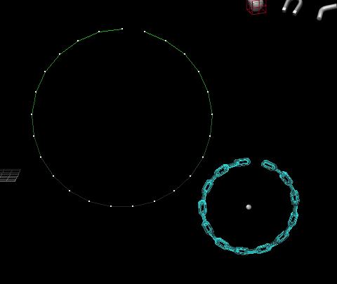
Now comes the fun part. The chain is of course a straight line. We want to shape it along a circle, or even bend and shake it loose. Draw a circle. Use many points (25 or more). Select the chain as the current object, then use the Bend tool from the modeling toolkit.
|
|
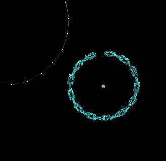
After clicking the bend tool, select the circle. The chain (our current object) is shaped accordingly. Note that the first and last links are not at 90 degrees, because we used an odd number of counts on duplication.
|
| Note
also that there is a gap of one link.
We may have to do this differently if you want to actually use an odd number to match at 90 degrees and have the circle of chain links come to a close. If
you want to deleted a line segment and open up the circle, use the 'Delete
Faces' tool from the
|
|
If you apply the bend tool to the straight chain in such a case, here's what you get. Still not perfect.
|
|
Before applying the Bend tool, you can use the Stretch tool to manually move the few points closest to either end over the limit for a partial overlap. 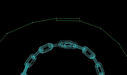 |
| Here's
another interesting example: Instead of using a circle for the shape,
I used the Spiral curve (second icon from the right in the 2D draw palette). Look
at this, the two end links come to a touch. If we had used an odd number
of links on the
|
| Time
to talk about rendering. If this chain is to lie horizontally on a table,
we need to rotate the end links a bit down so the rest on the ground.
Be sure to 'Ungroup' the chain so each link can be selected alone. Then rotate either end link on its 'attached' end. Using the rotate tool from the assembly toolkit is easy, and if you're not picky you don't even have to worry about the rotation axis being along the main axis and not exactly perfectly aligned for the link's axis. However, you can also change reference planes (there's a tool for this in the lower-left corner of the control panel) and temporarily work in the link's reference plane system for a perfect rotation.  |
|
Time for a little more visual realism. Use the CONTROL-A key (or Apple-A) to select all links again (or Group them one-by-one or with the lasso cursor). Enter the Shader. Be sure to use Extended editor mode there, or 'More Parameters'. Add
a layer (middle-lower right) for an Image texture.
For the Mapping, use 'Reflection'. That's short for environment reflection texture mapping.
|
|
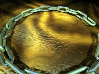
Here's a cool preview. See the effect of the environment map on the metallic looking links?
|
|
Now I decided to place the whole thing on a plate and a table. I also will place several lights there, apply various materials to the table and plate. Using a side view, you can draw a profile for the chain to adopt as a result of it being laid over the rim of the plate. Use the Bend tool again for this final touch.
|
| Here's
a first render in progress. Ouch, the table's ambient color is too high,
I see the edge of it.
I want to make it disappear into total black darkness instead. 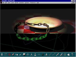 Also,
the plate is too bright, I need to reduce the diffuse color.
|
| How's
that?
|
[ back to start of tutorial ] [ back to top ]